Choosing LEDs and Updating Design

This is the second post about BUSY BAR. The beginning of our journey is here.
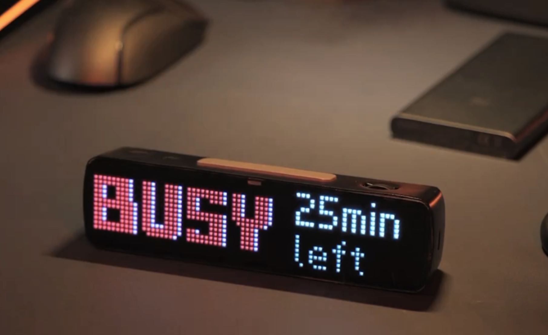
BUSY Bar is a portable LED panel that visualizes the user’s active status and can serve as a Pomodoro timer.
We’re building it for productivity and creative minds. With an open-source approach and an API, it’s an enhancement to the user’s workflow.
From this article, you will learn:
- How we selected LEDs for the display
- How LEDs being chosen affected the device’s design
- How we improved the indicator light and brightness sensor
- What we decided on a cover for the back OLED display
- The Aha! moment
In the following articles, I’ll guide you through the process of crafting our first working prototype, discuss the current phase of the development, and into the features we’ve put to the test.
Choosing LEDs for the display
At first, my idea was to create a small standalone panel that could be easily carried in a backpack or pocket.
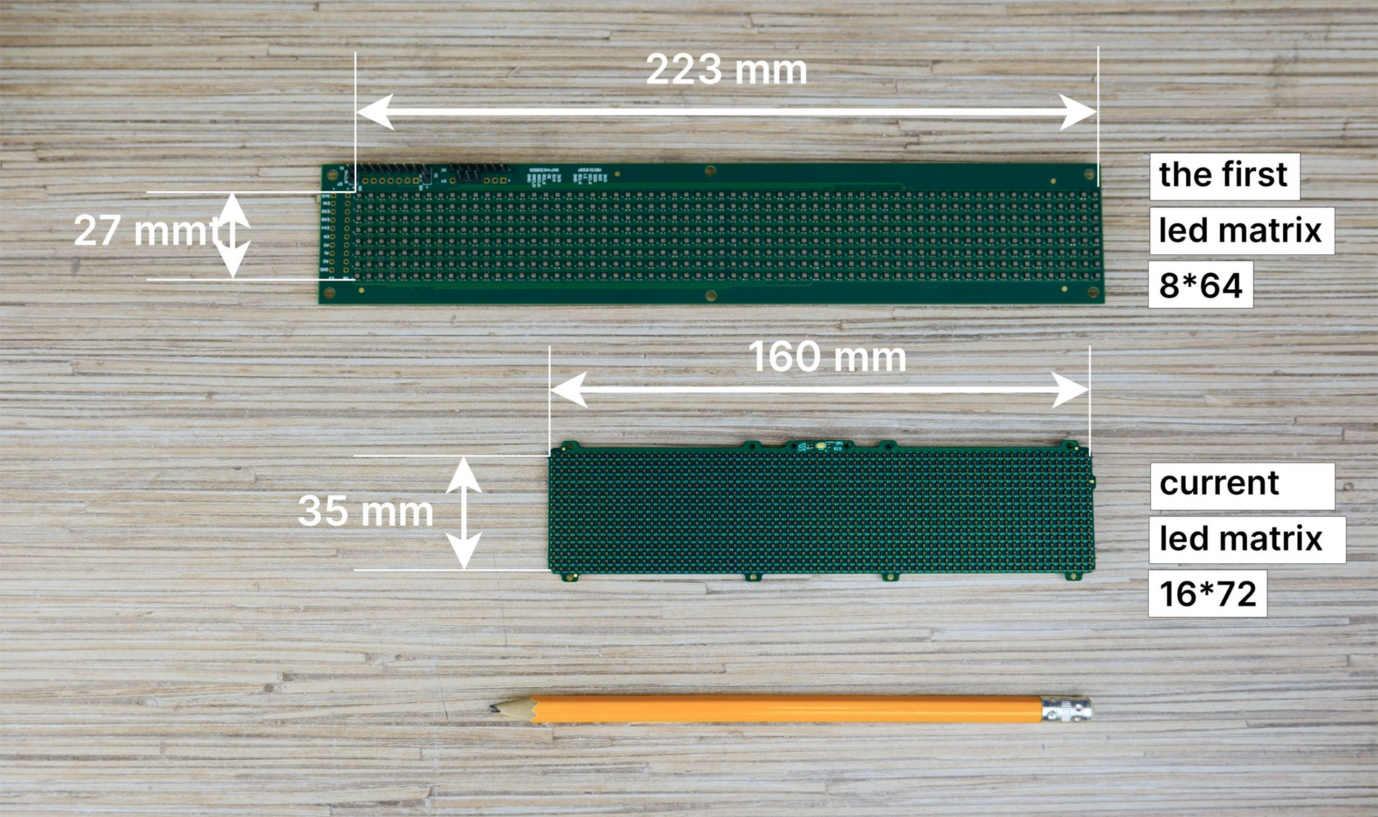
The LED matrix determines the size of the device. Therefore, it was important to select compact LEDs that offer excellent brightness.
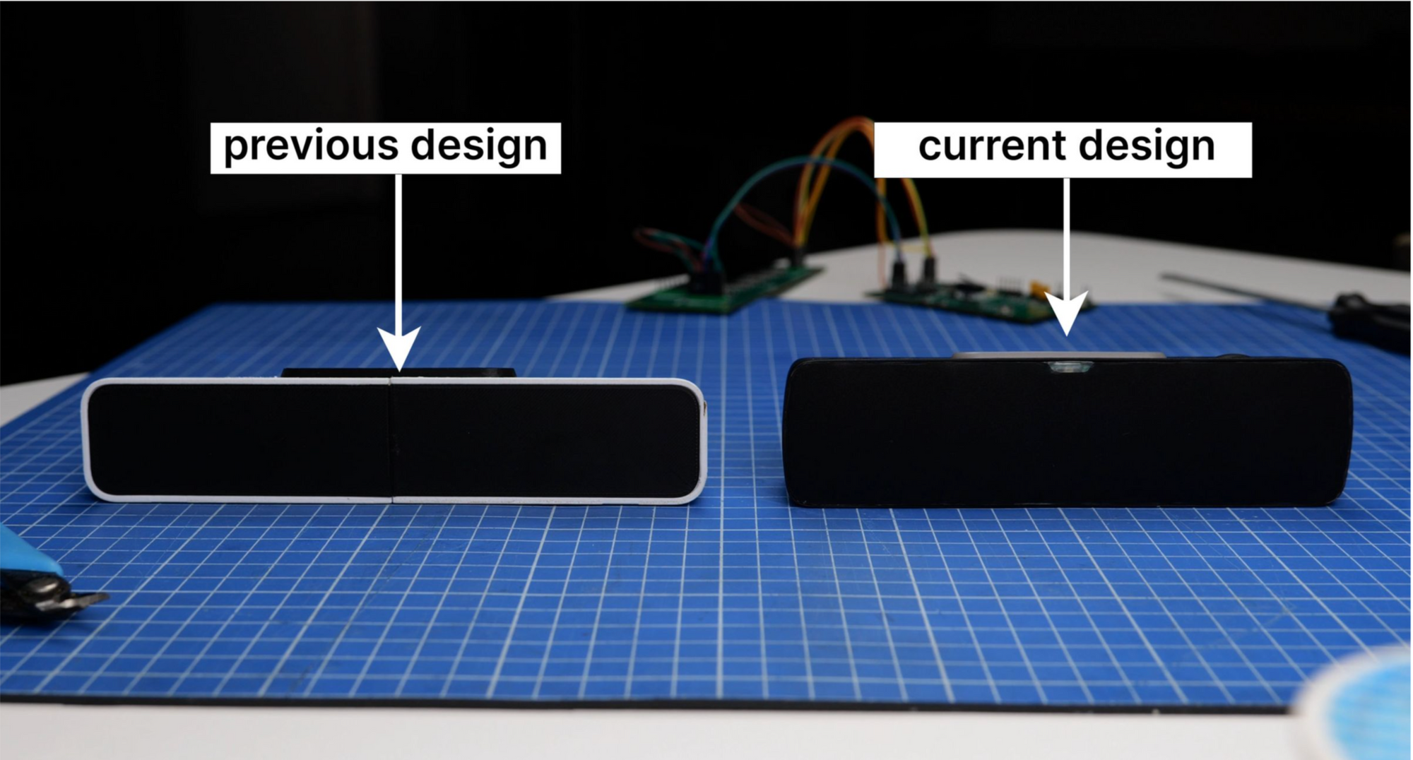
The original matrix was 8x64 pixels: 2.1 x 2.1 mm LEDs at 1.6 mm apart. However, that size made the device non-portable. Here’s a comparison picture with our current, smaller prototype.
During the selection process, we targeted LEDs smaller than 2 mm for a denser matrix and a more compact device. After considering options based on size, brightness, and cost, we prepared a comparison table for mass production.
| № | Part Number | Size, mm | Price for 1152 pc. (16х72) | Max. brightness | ||
| Red | Green | Blue | ||||
| 1 | P4-1010RGBTA1-0.4T-A | 1x1 | $26.68 | 140 | 400 | 120 |
| 2 | MHPA1515RGBDT-S | 1.65x1.55 | $46.89 | 800 | 1100 | 130 |
| 3 | 18-038T/BDGAR6S1-S06/10T | 1x1 | $66.5 | 94 | 300 | 60 |
| 4 | NH-B1212RGBA-HF | 1.2x1.2 | $9.72 | 58 | 175 | 25 |
| 5 | NH-B1010RGBT-HF | 1x1 | $10.56 | 35 | 55 | 10 |
We used a specially designed board to assess the brightness and color rendering of the selected LEDs: 8x8 pixel matrices for the selected LEDs, covered by a 25% transparent tinted film. We displayed various characters to compare brightness and color. LED No.2 was the brightest, but at a kit cost of $50, the retail price for a single BUSY Bar would start at $400. It does not work for us. LED No.1 was also bright and compact, but similarly unaffordable.
Upon reviewing, we focused on options 4 and 5, differing in size and brightness. Eventually, option 4 was chosen, favoring size over brightness. After some bargaining with the manufacturer, we secured a $4 price for 1152 pieces. Having decided on LEDs, we can move forward to changing the design of BUSY Bar.
BUSY Bar design revision
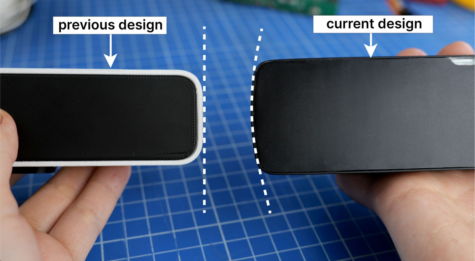
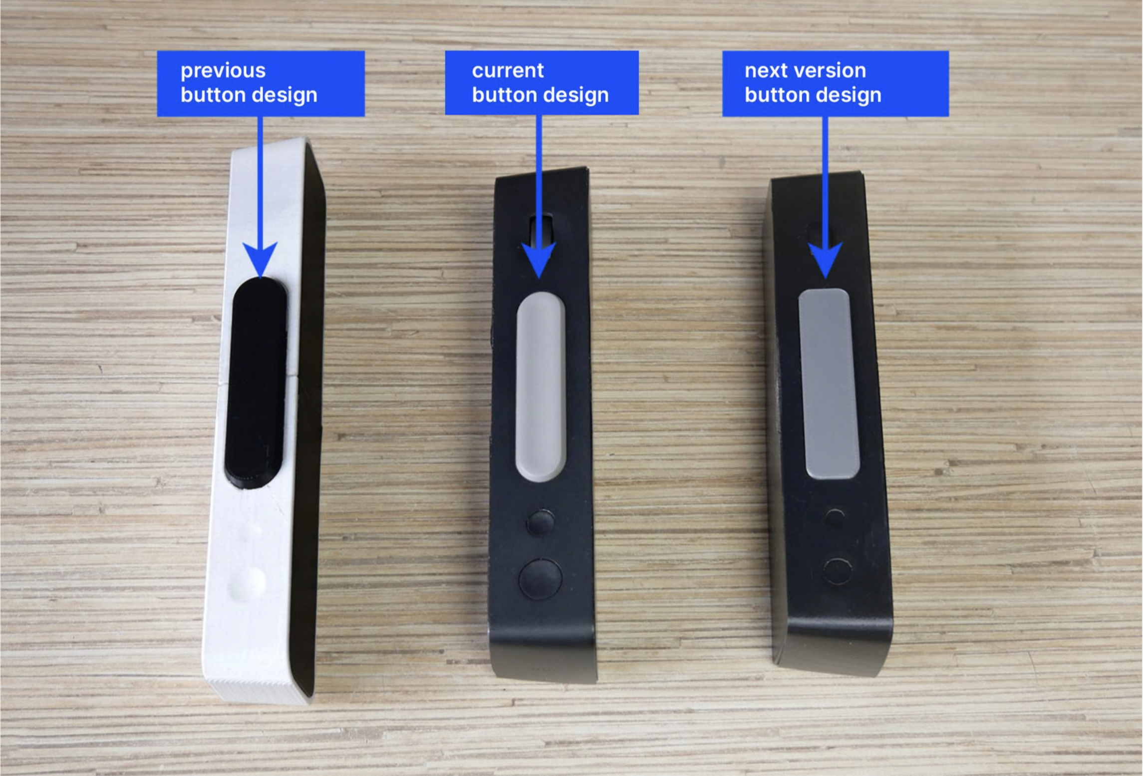
In the initial design, I envisioned a rectangular device with rounded edges that thin towards the back. The primary body color was white, chosen to contrast with the front screen and the large button atop the device.
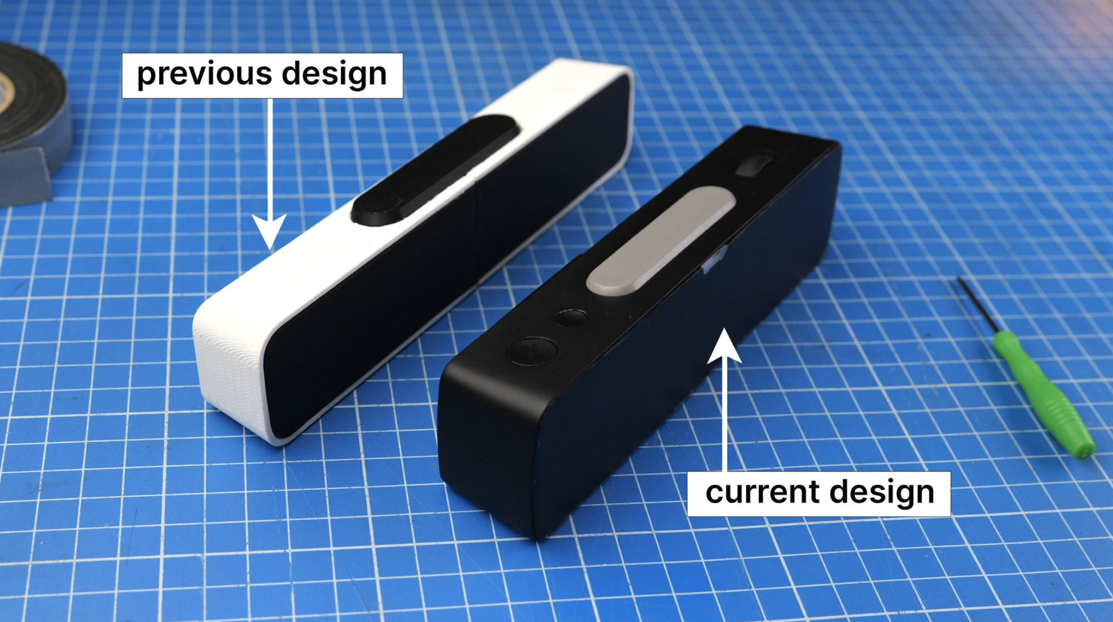
In the refreshed design, we’ve curved the sides for a rounded look, making room for an internal speaker, thus augmenting its sleek and functional appeal.
Leveraging compact LEDs, our device changed in size and shape — sleeker yet taller. LED rows have elegantly doubled to 16, with columns expanding from 64 to 72, amplifying resolution in a compact design.
Keeping the large button’s form from the initial design didn’t harmonize with the device’s sleek lines upon hands-on inspection. Thus, the upcoming iteration will feature a subtly larger button with a rounded-rectangular shape, ensuring a seamless, unified design aesthetic.
Design of the indicator light and ambient light sensor
On the back of the device, there is an indicator light that provides users with information regarding its active status.
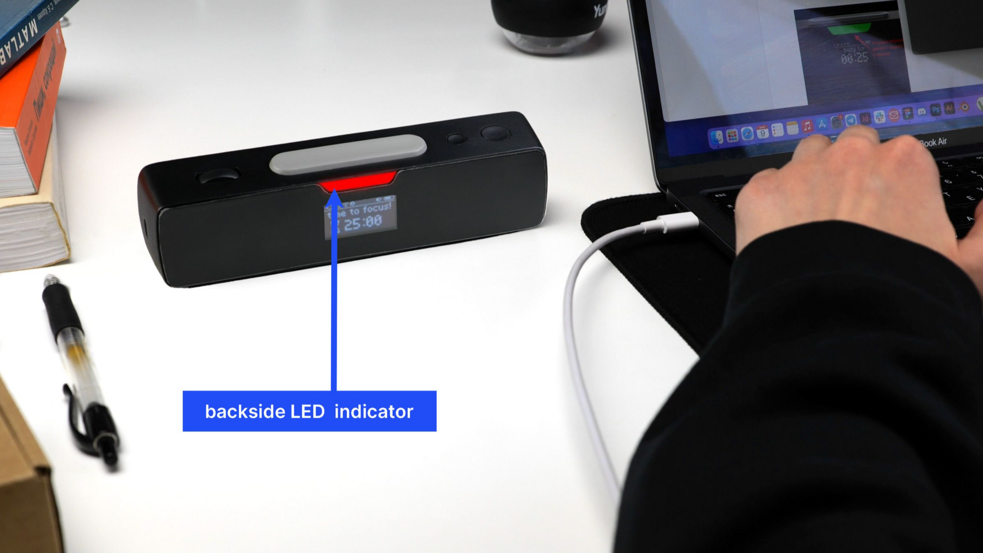
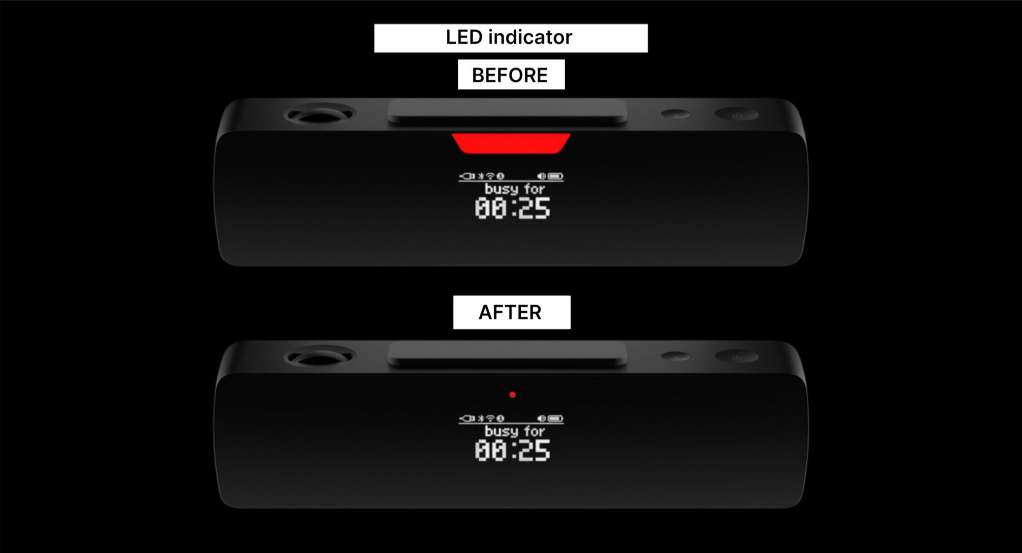
In the existing design, the oversized indicator opening and its uniform illumination posed challenges, as revealed by the prototype usage. The next iteration will introduce a refined, smaller, round opening for enhanced functionality and aesthetics.
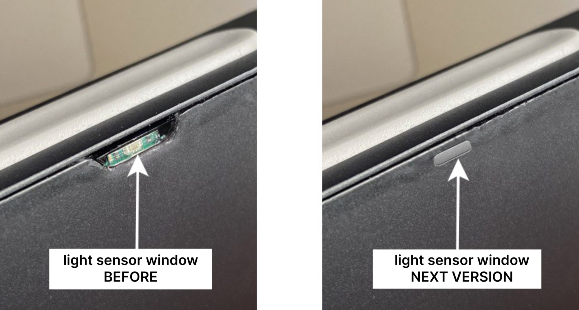
We’ve installed an ambient light sensor on the device’s front for automatic LED brightness adjustment. The sensor’s window design is similar to the light indicator’s back window. However, after assembling the prototype, we found it to be too large, revealing the green color of the board housing the sensor. In the next iteration, the window will be smaller and have a different shape.
Selecting a cover for the back OLED display
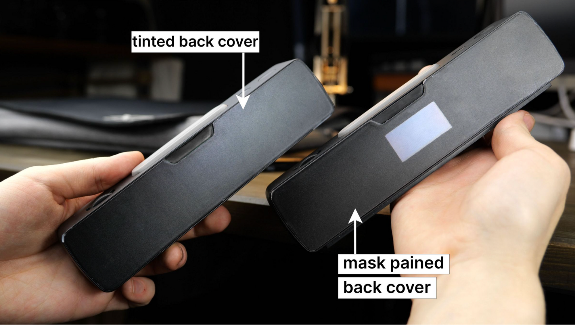
There is a 1.16″ OLED display located at the back. It shows remaining time, battery level, and device connections. The display is underneath the back cover, and currently, there are two possible cover options:
- A tinted-in-mass cover that hides the display frame when turned off. However, when turned on, its brightness needs to be increased for better visibility, affecting its lifespan.
- A fully transparent back cover with a black mask applied, leaving only the display’s active zone behind the transparent plastic. This solution extends the lifespan but reveals the display frames when it is turned off.
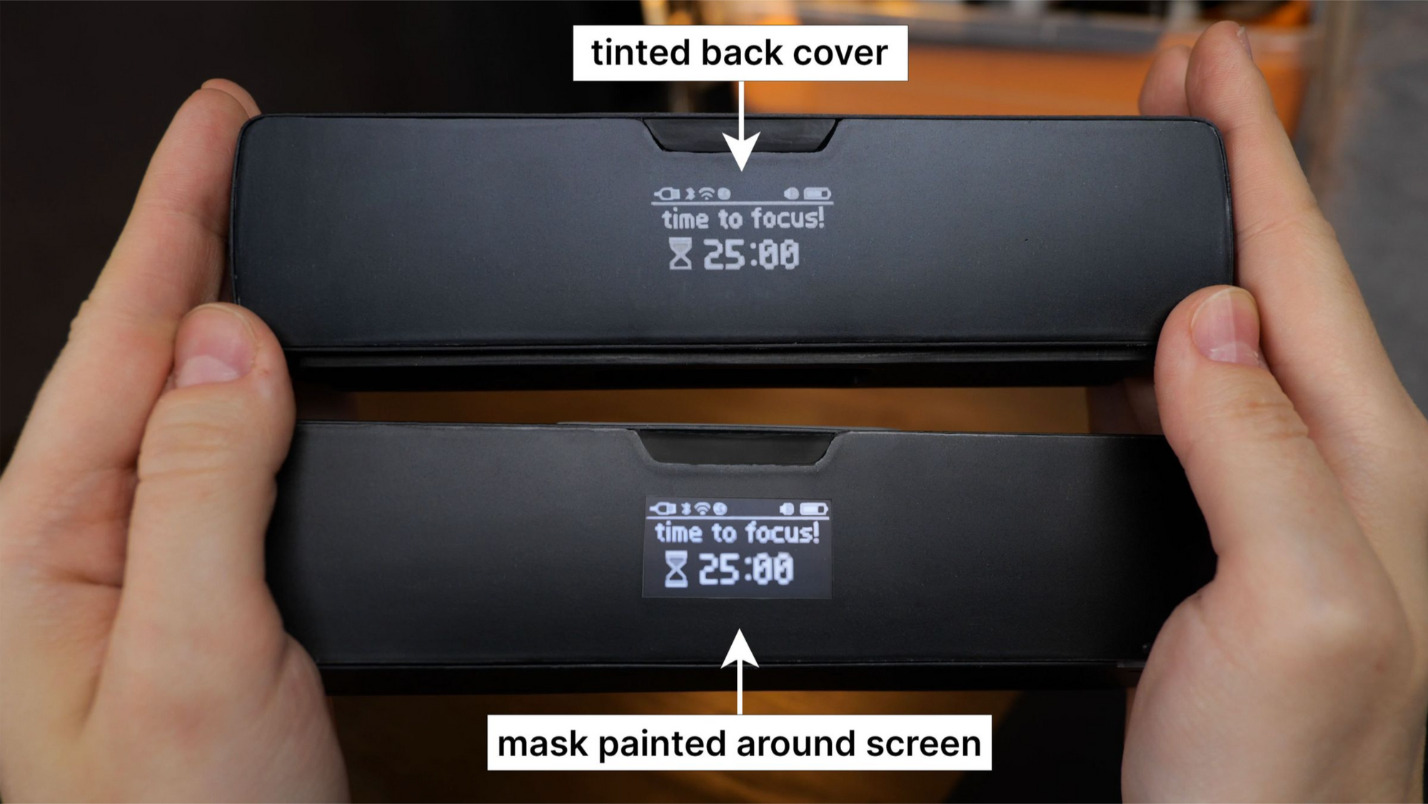
With the tinted glass, the rear surface appears uniformly dark when the display is off, while the masked option reveals the display frames, resulting in a mixed impression. Which option do you prefer? Currently, we lean towards the tinted cover without frames.
Aha! Moment
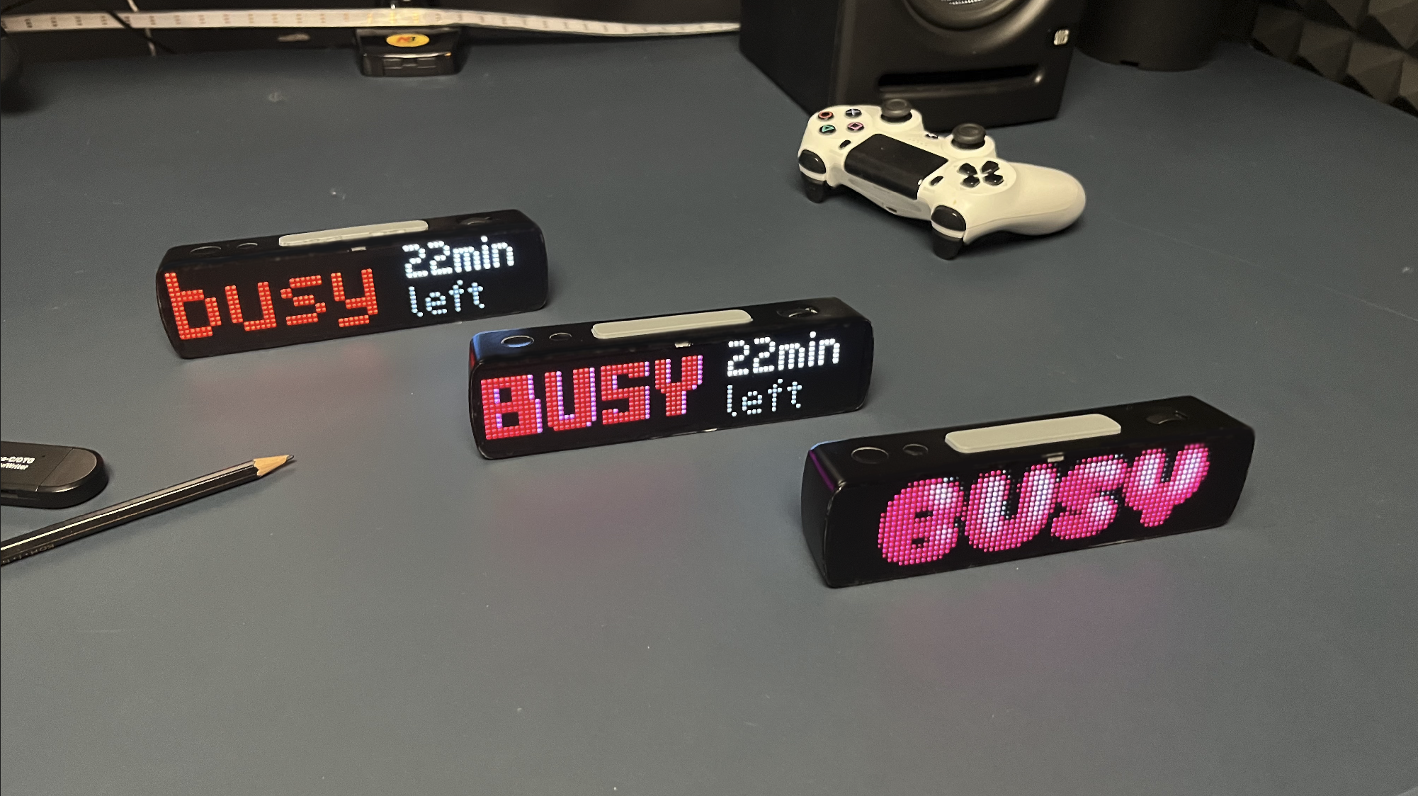
As soon as the prototype could work as a Pomodoro timer, we rushed to use it. It was very useful to start working on the UX. However, we knew that the device should spark joy.
So we tested some nice lettering, and it was awesome!
This is not the entire progress we’ve made over the last 6 months. The upcoming articles will cover:
- How we developed the mechanical and electrical components
- The initial lines of code we wrote for the device
- How we assembled and tested the first prototypes
How to buy?
We have exciting plans to bring the device to market through a crowdfunding campaign on Kickstarter, which we plan to launch later this summer. We hope to ship the finished devices six months after the fundraising ends.