Assembling and Launching the Prototype

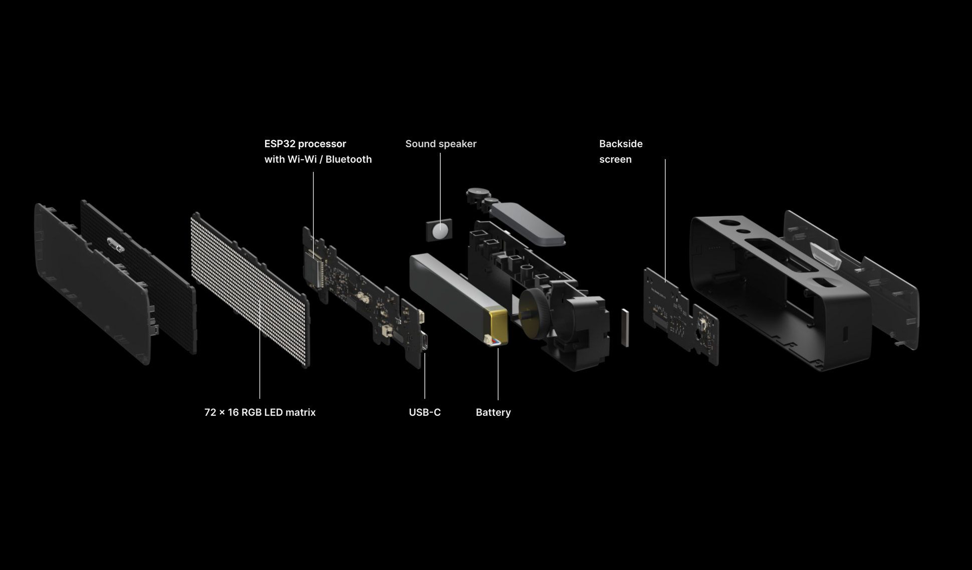
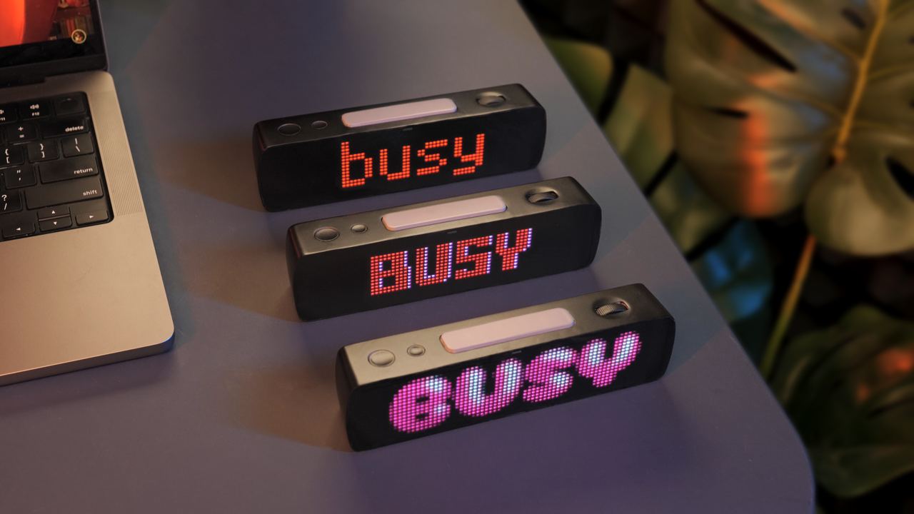
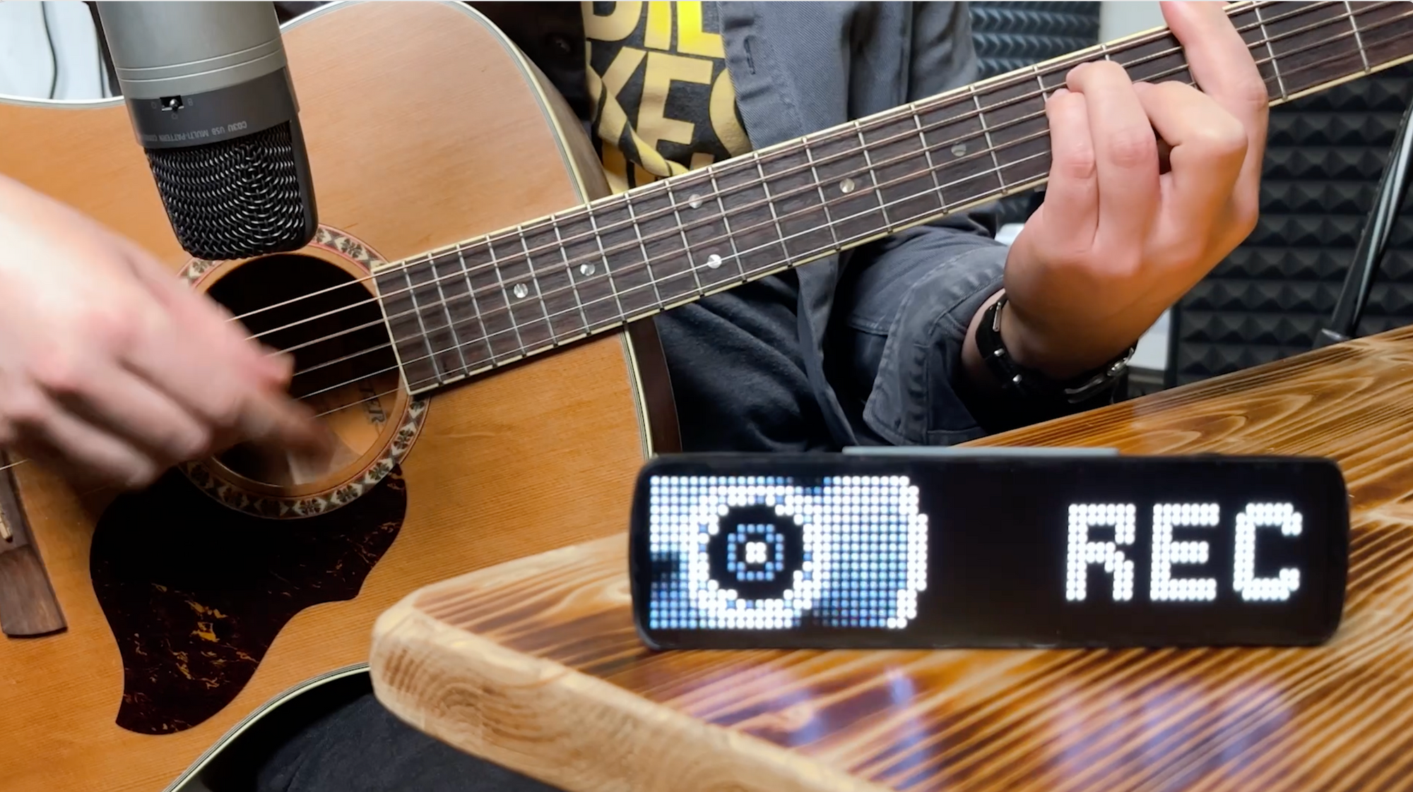
BUSY Bar is a desktop LED display that beautifully communicates to others things that matter to you. Show that you’re busy, activate a Pomodoro timer, or display inside jokes to your friends.
In this article, I present an overview of BUSY Bar prototype assembly, an innovative use of automotive tint film, and the coding that brings the device to life.
I covered the device design process and choosing components in articles [1], [2], and [3].
Assembling the working prototype
I was in a hurry to build the first prototype. I ordered parts for several prototypes from China. Making the boards correctly on the first try didn’t work out.
LED contacts soldered together
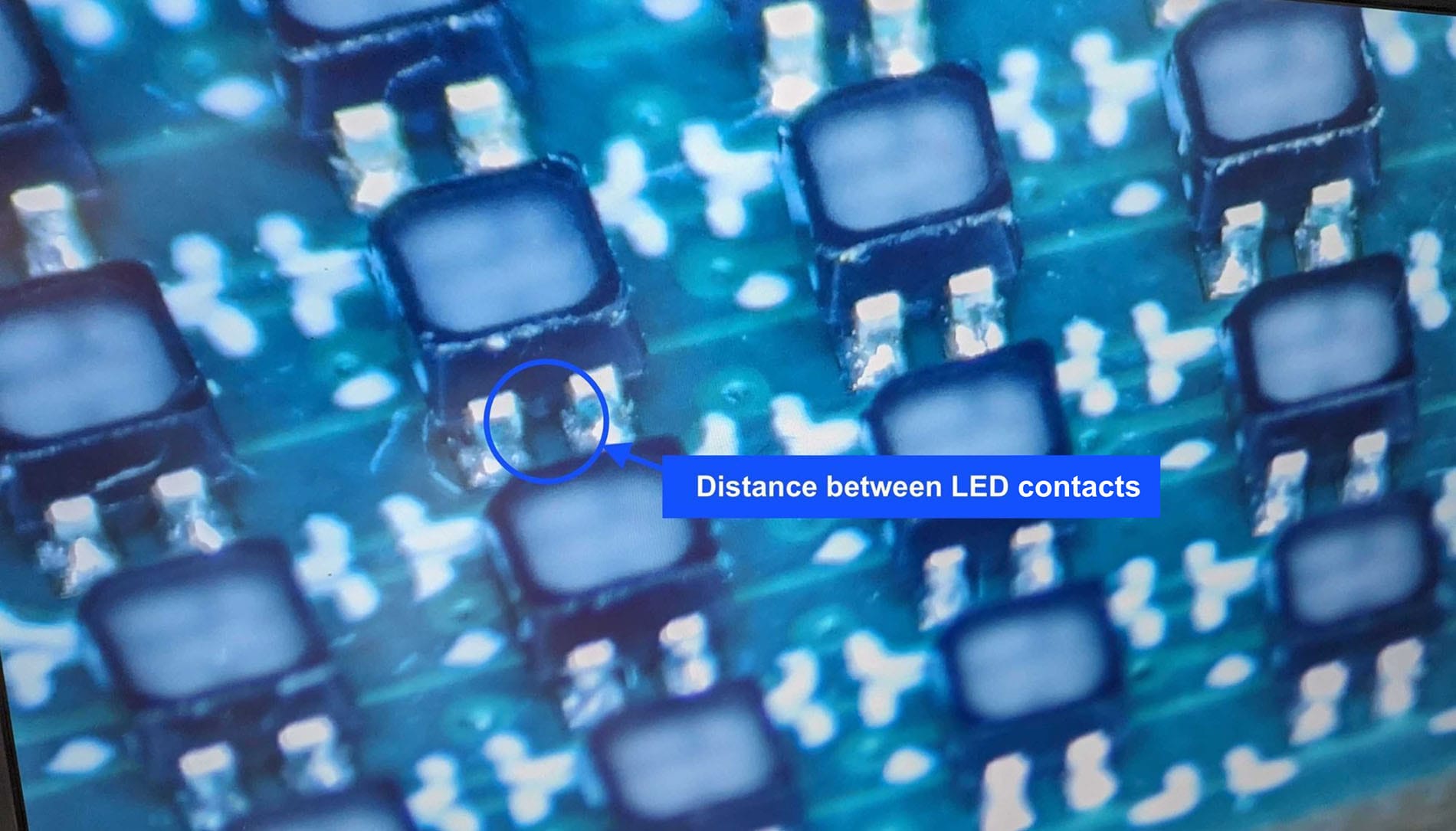
Some scroll wheels (aka encoders) were misaligned. And some LEDs had neighbouring contacts soldered together.
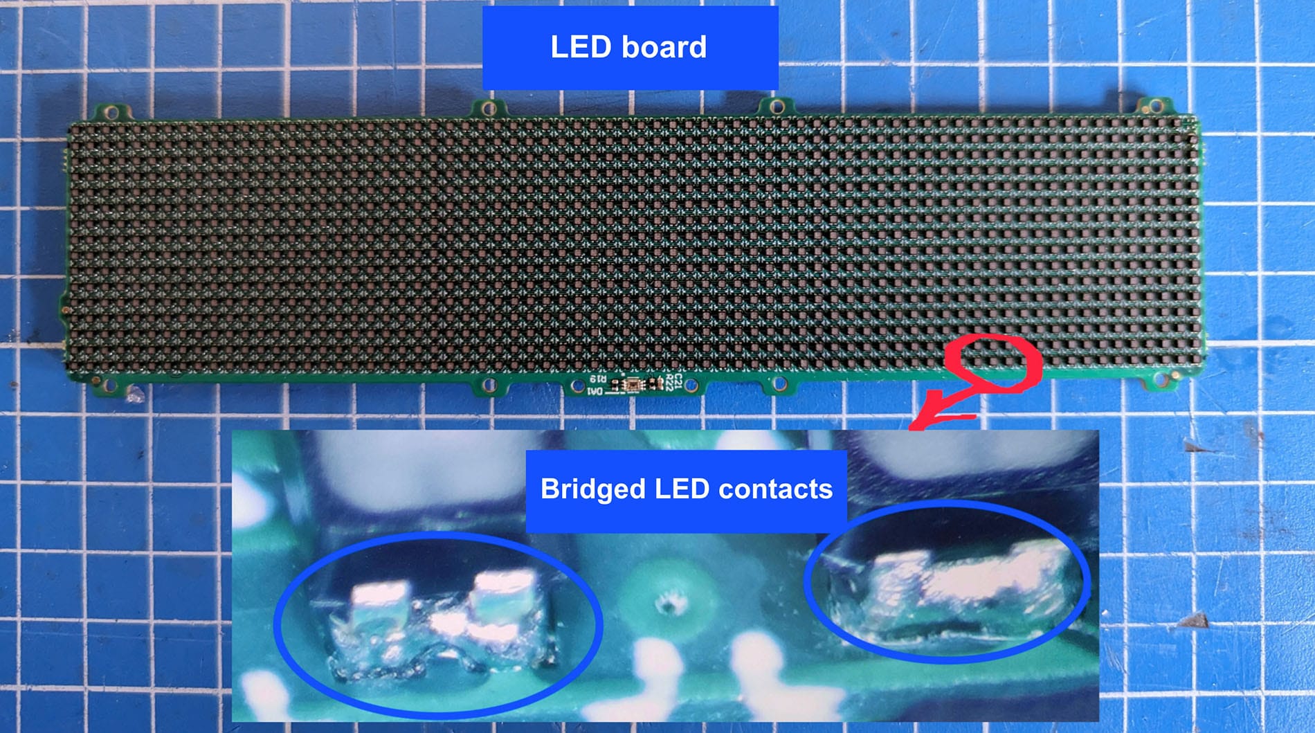
I wasn’t discouraged and removed the bridges between LED contacts manually using a soldering wick.
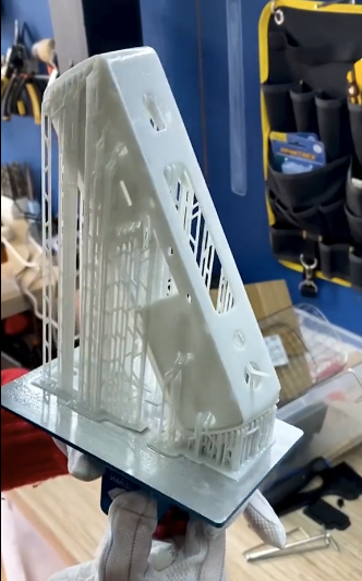
Precise casing printing
Casing parts were printed using stereolithography (SLA) printing. With SLA, I printed all the latches so precisely that we were able to assemble the prototype almost as it will be in mass production.
Automotive tint film for display
The casing and small buttons were immediately painted black. Only the front and back covers were left transparent. So, I tinted them with automotive tint film.
I tried films with different shading and settled on 25% of light transmittance. Since the film was glossy and the casing was matte, I also applied a matte film over the tinting.
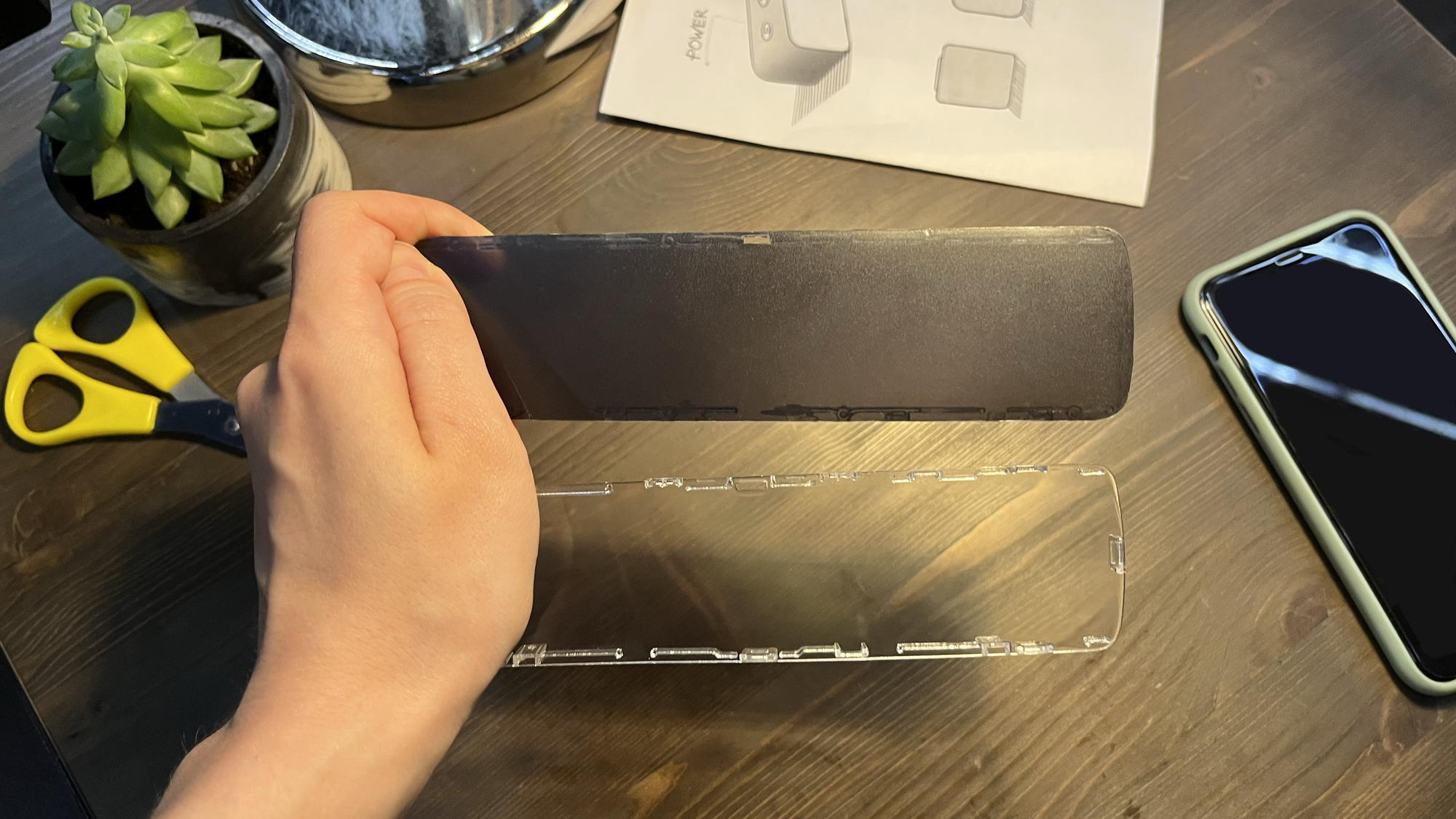
If you’re about to write that we did everything wrong, please do. We’re looking for a technology to produce transparent but tinted panels in a single copy. I would be grateful for your help.
Assembly process
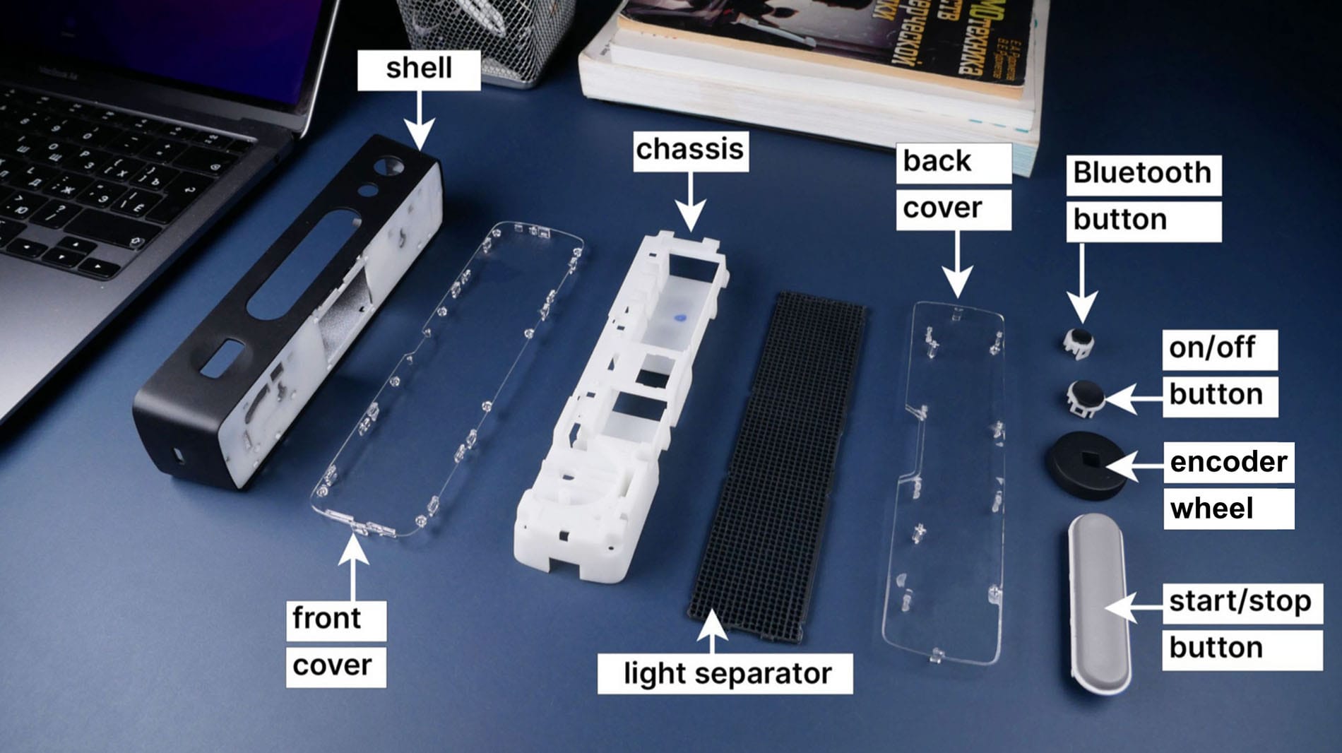
Assembling the device takes 5-10 minutes. Boards are screwed to the chassis and display. The display and rear cover are held in the casing by latches.
Initially, it was hard to fit the chassis into the casing, as we had to jam buttons in. The more complex the assembly, the more expensive it is.
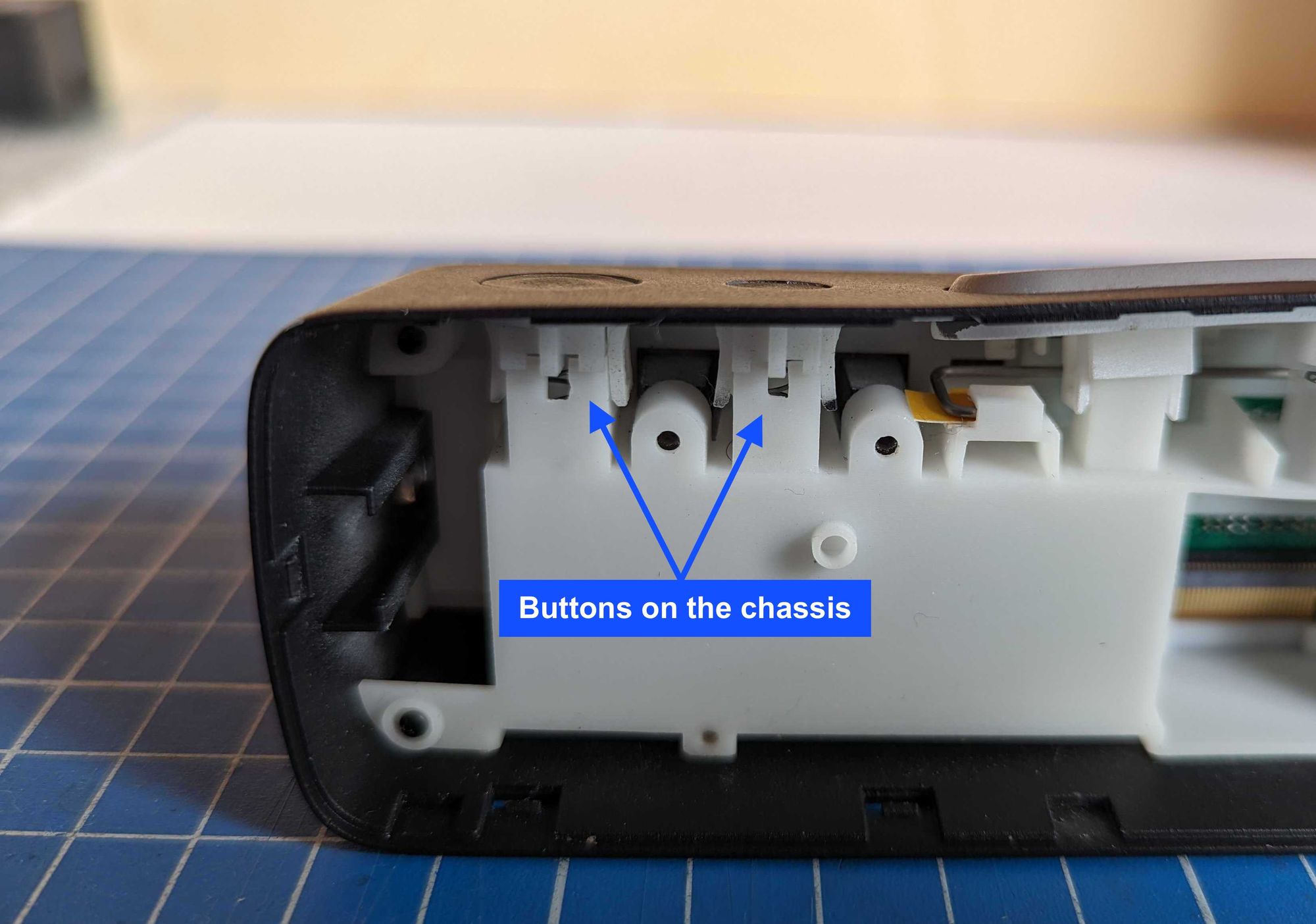
Therefore, we changed the design to simplify the assembly process: placed the buttons on a separate board with microswitches.
[Video] Assembly of a later prototype on TikTok
Breathing life into BUSY Bar
Okay, we now have all the parts to build a prototype. To get all the components up and running, we assembled a test stand from ready boards without casing.
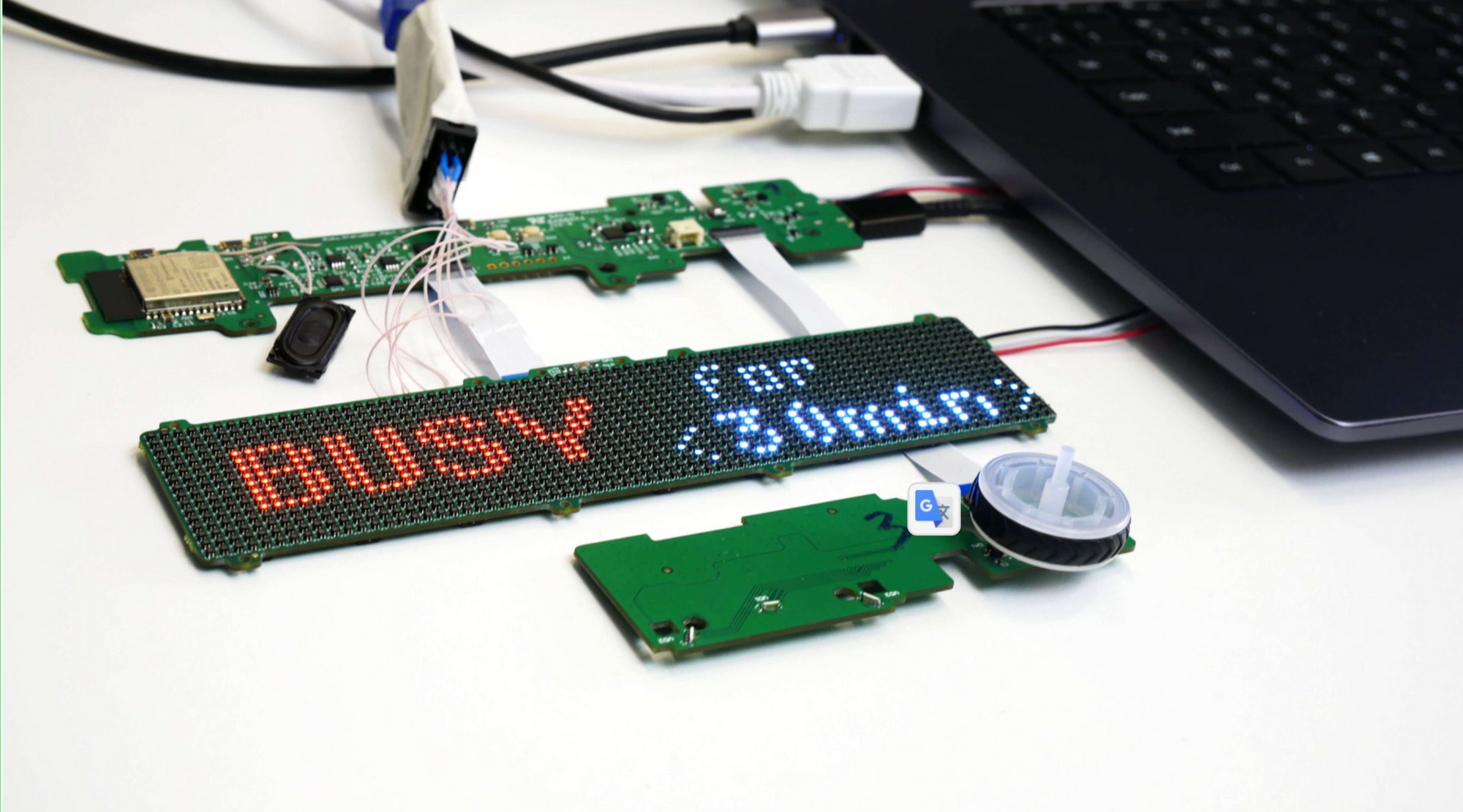
For software development, we use the ESP-IDF framework, which is the standard library set for our ESP32 microcontroller.
The code is needed to run almost all of the device’s components: the LED display, charging module, encoder, buttons, light sensor, rear display, and speaker.
How to craft a bright and vibrant display
What do you imagine a typical LED board to look like? Something like this: few colours, only two states of a diode (on and off).
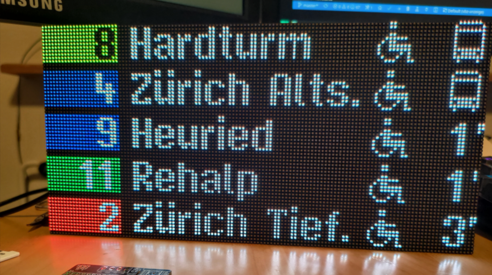
We want to make the BUSY Bar display to be bright and beautiful.
So, we had to learn how to control the color and brightness of each diode separately. Now, several MBI5253 drivers control the diodes on the LED panel. Such drivers are used in large LED panels to fully control RGB diodes.
But to control the diode drivers, our ESP32 chip uses the standard SPI. However, the MBI 5253 drivers do not have that type of interface. Therefore, our developers learned how to use the SPI interface in a non-standard mode.
Mapping the UX prototype
Here’s the map of the first UX prototype with the status display function and Bluetooth on/off.
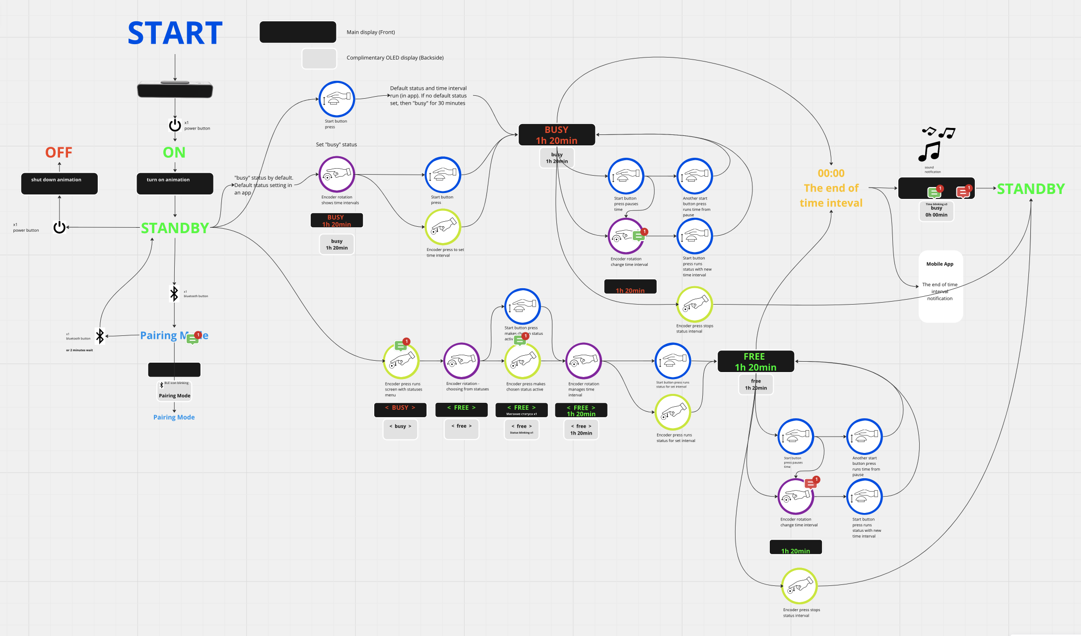
In accordance with the UX map, we designed the screens and uploaded them to the device. To render graphics, we used custom-written code, only taking a standard font from the U8G2 library. U8G2 is commonly used to create graphics for monochrome displays.
Status selection (first version of the UI)
Simplifying Bluetooth pairing
We made a draft Android application and enabled communication between the phone and the device via Bluetooth.
I want to make pairing with the phone as simple as possible — without entering codes or connecting like a hotspot. So that the user can press the Bluetooth button on the BUSY Bar, and the device is visible in the app for a couple of minutes, then the devices pair.
I want to make pairing with the phone as simple as possible — without entering codes or connecting like a hotspot. The user should be able to press the Bluetooth button on BUSY Bar, and the device will appear in the app for a couple of minutes, then the devices pair.
[Video] Connecting to Android
The panel remembers the phone and maintains a connection with it as long as the phone is within range.
After pairing, the app allows the user to manage Wi-Fi connections, enabling them to connect BUSY Bar to Wi-Fi with just a few clicks.
We tested the connection to Wi-Fi access points and confirmed that Bluetooth and Wi-Fi can work simultaneously.
Animations
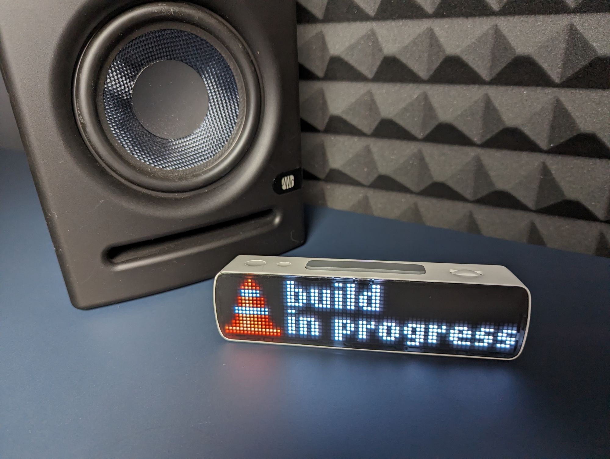
Once we had the prototype ready, we tested the animations
Now we’re uploading animations to the device as a sequence of PNG files. We’ve achieved around 90 fps animations without flickering.
What we like most as a team is seeing how the device comes to life with new animation. Check out interesting animated statuses we’ve already prepared.
Suggest your animations, and we will bring them to life in the next articles.
What’s Next
From a hardware perspective, the device is almost ready. We only have to figure out a few details and see the updated design of the next prototype.
As for software, we have an exciting journey ahead:
- Building the mobile application. App users will be able to upload more applications and control BUSY Bar remotely.
- Enhancing firmware code for future scalability. We recognise the need to rebuild the code architecture to avoid future limitations.
- Integrating external services. BUSY Bar will be able to change the status based on Slack statuses and Zoom calls.
Previously, we announced that the source code will be open. We’ll post it on GitHub later, it’s a bit raw at the moment.
We plan to crowdfund the production of BUSY Bar on Kickstarter. We hope to ship finished devices six months after the campaign ends.
More use cases and scenarios on TikTok | Twitter | Instagram